THE "OLD" CRUISE-A-HOME FIXIT BOOK
September 1998
The Fixit Book is primarily for Cruise-A-Home owners who need to find replacement parts and/or repairs for their out-of-production boats. It was designed for the "old" boats, before the updated Corsair was built, but many of the items are applicable to the "new" boat, or even other boat makes as well.
I don’t update this list too often. Obviously, suppliers change product lines, prices, etc., so if you find a supplier here who no longer carries the desired product (or a new one who does), please let me know. Thanks.
Good luck, and happy cruising!
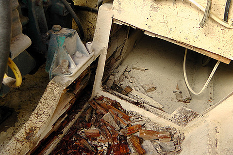
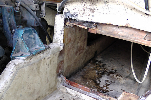
Repairing "Soft" StringersBy Charles Fox |
|
|
I have gone ahead with repairing the forward engine beds/stringers. It is possible to do it in the boat without removing the engines. I first supported the engine with 2x4s cut to fit under the engine mounts, then took an angle grinder with a cut off wheel and "skinned" the side of the stringer where there was a dull sound. The wood was dry but rotten. It pulled out easily. I then cut wood to fit in the space, trying to scarf it in and offset the joins. I then saturated the wood with epoxy |
and filled any gaps with epoxy and fiberglass cloth. I then replaced the fiberglass "skin" taken off previously with a lot of thickened epoxy and screwed it in tight to set. After setting, I removed the screws and built up another layer of cloth and epoxy. I finished it of with some marine enamel to look nice. After rebolting the engine mounts, it is as solid as it gets. A messy but doable job. |
 |
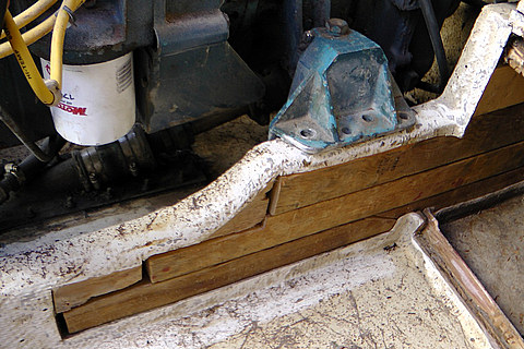 |
| "Skinned" the stringer | Fit in the space |
 |
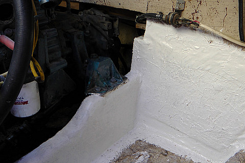 |
| Covered with cloth and epoxy | Finish off with marine enamel |
Cruise-A-Home bridge back-to-back chairsFrom Dean Singer |
|
|
These seats are a product that was designed and developed as a cooperative effort with Cruise-A-Home and Tempress Inc. of Seattle in the mid seventies. Prior to starting CAH Warren was in the marine accessories business with a company called Middy Marine Products. One of the product was a "Foam in place seat cushion" which he developed in the mid 60's and was sold to a number of builders. The parent company was acquired by Dart Industries (Rexall Drug & Chemical) and the Middy division was sold. The new owner did not follow on with the product and it faded away. In the Mid 70's a tool and die company called Tempress Inc.in Seattle owned by Del Brink a boating enthusiest who had the original Middy seat in his boat was entering the marine business. Warren and I worked with them to redevelop other the seat cushions and |
seating systems such as the bases and arm rest frames etc. using structural foam and aluminum castings. The short coming of the foam in place seat cushion was that it required non-reinforced vinyl to vacuum form the skin prior to injecting the foam. This type of vinyl was available largely due to the volume required by the automotive industry. As auto interiors changed and evolved to new materials the demand for these vinyl products declined and the market dried up. There was not enough volume demand in the marine market to make it feasible to manufacture this product. Too bad, it was a great product and idea as there were no seems to leak and rot, look how long they lasted.... Your best bet now is to have some cushion covers made to replicate the old ones or cover them as close as possible. |
Railing Replacement:Don Whiteside reports: |
|
|
The rails on my boat were made by Hollaender Manufacturing Company. Their brand is "Speed-Rail" and is still manufactured and sold. The CAH rails are an odd size if you try to buy at a marine store. Technically, they are 3/4" IPS (Iron Pipe size) which have an O.D. of 1.05". The fittings (base and other) have an I.D. of 1.070. Folks think these are "slightly large" 1" rails, but this is a mistake. The companies listed in the "Fixit Book" are no longer dealers because they didn't stock the product. They told me the parts are no longer available, but this is not correct. |
You can contact Hollaener at 800-772-8806 or www.hollaender.com and they will sell direct if there is not a dealer near you. They connected me with a dealer in San Francisco who will order any of the parts I need. As an example,the rectangular base that is used on the top deck, and to repair posts on the gunnels, is about $6. They also sell the correct size aluminum tubing, but it is not anodized. Their catalog shows all the little fittings, pieces, etc. One note- if you download and print the catalog, the sizes are not "true". The actual catalog I got at the dealer has true sizes for comparison. |
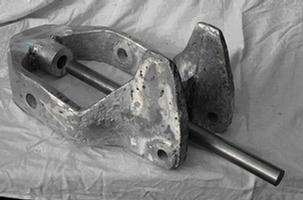
SOME TIPS ON SAVING PARTS ON OLD OUTDRIVESFrom Randy German |
|
|
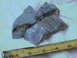
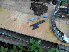
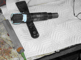
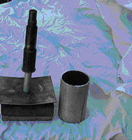
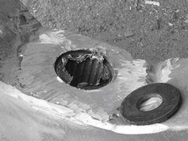
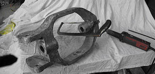
Parts for the Type III Mercruiser outdrive are non-existent, so when the gimbal ring of the one on my CAH disintegrated, I was a little disheartened. Large chunks of metal broke out of it when I raised the lower unit to change the zinc. Consulting with the local experts confirmed that the supply of parts for these is entirely used up, even in other parts of the country. A relatively simple method of repairing the aluminum casting materialized however. The crux of the problem lies in the fact that the broken section contains a hole with internal splines; creating a difficult machining job. By using the intact steel shaft with its external splines as part of a mold, the new hole was cast into a cylinder of aluminum and then welded into the useable part of the gimbal ring. Some problems needed to be overcome. The steel shaft has a horizontal slot for a cross-bolt and slots in its sides, as well. These need to be filled with material which will resist the heat of molten aluminum. The shaft must be cleaned of all oil and grease as they would burn and gas under heat. Plaster of paris is used to fill the slots and grooves completely; no undercuts can be left in the surface of the shaft splines, or the shaft will never press out of the new cylinder of metal cast around it. A thin file is used to carefully match the plaster to the existing splines. The plaster must be thoroughly dried, baked even. Several hours and a hair dryer or oven should remove all traces of water from it. Graphite or talc powder can be dusted onto the finished shaft to help it release from the casting. I wrapped two layers of thin aluminum foil around the shaft, very carefully working it into the splines. This took two tries to get right. Use a plastic blade with curved ends to form the foil. By holding the foil over the grooves you can avoid moving it as you make the next groove. Wrinkles can be smoothed flat, but the foil won’t stretch. The foil helps protect the steel of the pin from heat damage as well as enabling the separation of the casting after it shrinks around the pin. Don’t use tape or anything else to hold the inner or outer edges of the foil. The foil can be folded under at the bottom of the pin and wrapped with clean uninsulated wire at the top, above the splines, to hold in position. The portion of the pin above the splines is a bearing surface for the needle bearings in the gimbal housing. Extra wraps of foil there would be a good idea. I poked small air holes through the foil at the top end of the splines to enable gases to escape during the casting process. The pin was held upright in a piece of 3" dia. aluminum tubing, allowing an extra 2 1/2" inches of length so the casting will have room for a socket to be machined in its bottom end. This socket is to locate the casting in position to be welded. A 5/8" fine-thread bolt held the pin vertically. A piece of 2X6 softwood with a 5"X6" piece of stainless steel plate 1/8" thick held the bolt upright. This was a mistake. The wood charred and the thin plate bowed ½" from the casting heat. A better method would have been to use ¼" or thicker steel plate. A 2 1/2" long piece of 1" dia. aluminum tubing was around the bolt to locate the pin the correct distance from the base, as well as to allow the bolts removal after casting. A steel washer was place above that tubing, just larger in diameter than the spline section of the pin. This was to aid in trimming off the socket portion of the casting after welding was completed. It also pinches the foil in position. |
At the foundry they packed foundry sand around the 5" high 3"dia. section of tubing which formed the outer part of the mold, locating it roughly centered around the pin held on its base. The foil covering the pin must not be disturbed during the whole process. After casting the new aluminum part, the extra metal slopped over the top of the splines was carefully removed so as not to damage the bearing surface. The center bolt and base were removed and the 3" dia. tubing can be slit and removed from the casting. The machine shop needs to: carefully clean up the top surface of the casting near the bearing surface of the pin; clean up the outer surface of the casting for welding, leaving a large diameter so welding heat won’t warp it; make the locating pin, in my case 1 ¼"dia. X 20" long steel bar; cut a socket in the casting bottom surface to closely fit the locating pin diameter. They will also need to press the pin out of the casting after marking both pin and casting, so the splines will exactly return to the same matching grooves. This all took two hours of shop time. When welding, the location of the new splined piece must be rotated so the steering tiller is exactly centered in the front side, and the top surface is where it was originally. Once the welding is started, the spline shaft and tiller should be removed to avoid heat damage. A plastic bushing around the locating bar at the bottom of the gimbal ring should be protected with wet rags while welding. The other plastic bushings at the sides of the gimbal ring should be removed. An exceptionally talented aluminum welder will be necessary to do a good job of attaching the new casting to the old casting. The old metal, even after cutting to make room for the new piece, holds contaminants which need to be burned out of the metal, and then cut down again. This took five hours of welding and cutting time. The process of removing the socket portion of the casting to leave just the spline portion on the gimbal ring was done with the hacksaw and a die grinder and cut-off wheel. Minimal clean up of the splines with a thin file was necessary. A coating of grease enables the pin to be tapped through the spline hole. One final job was drilling and tapping the hole for the cross bolt through the side of the spline pin. The welder saved a remnant of the original hole at each end. Using a series of long drill bits, the hole was made; tapping threads for it proved more difficult as longer taps are rare. Finally, a grade 8 bolt was tapered and grooved to simulate a tap, and cut well in the soft aluminum. The final product works well, and with proper lubrication and bonding to adequate zincs, will I hope last indefinitely. Union Foundry, Inc. |
 |
 |
| Pieces broken out of gimbal ring | Homemade wrench to remove nut at top of pivot pin, with broken gimbal ring |
 |
 |
| Filling the slots in the pin before shaping with file |
Pin on base next to 3" dia. tubing |
 |
 |
| Piece of plastic body filler spreader as used to smooth foil |
Gimbal ring with locating pin after welding |
 |
 |
| Foil still visible where it was pinched under washer |
Cutting off socket portion of new casting |
 |
|
| Grade 8 bolt as used as a tap |
Editors note: I have had good service from a marinized Delco alternator. It will put out up to 85 Amps and has a self contained regulator. They are available from:
Grafco Electric
34425 Pacific Ave S. 
Federal Way, WA 98032
(253) 517-7385
The 305’s are virtually non-existant, but several 350 c.i. alternatives are available: Marine Power Inc. in Louisiana, Volvo, Crusader, and others supply marinized engines at about $7000 plus installation. (Those of us with 305 c.i. engines have to re-pitch our props if we go to 350’s.) I understand that as of 1998, RH rotation engines will no longer be manufactured. For many of us, our port engine is RH rotation. Swapping to a LH rotation engine requires a different V-drive.
Richard Phillips reports that Jasper Engines still supplies both left-hand
and right-hand rotation engines.
Web site:
http://www.jasperengines.com/marine-products.php
| Coastline Equipment, Inc. 2235 Bakerview Rd. Bellingham, WA 98226 (360) 734-8509 | Contact: Tom Stabile They have the original drawings. $655 ea. in 2003 |

Here is a site that sells color matching paint:
http://www.spectrumcolor.com/